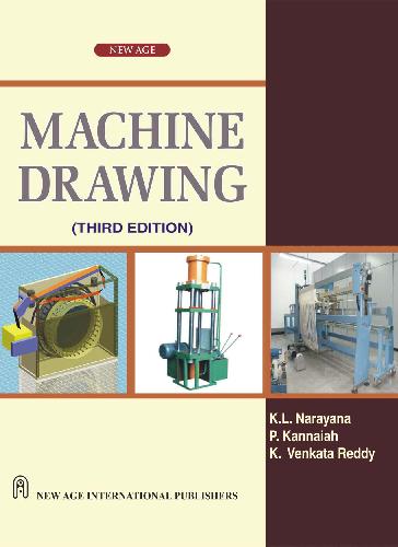
K.L. Narayana, P. Kannaiah, K. Venketa Reddy8122419178, 9788122419177
Table of contents :
Preface to Third Edition
……Page 8
Preface to First Edition
……Page 10
Contents……Page 12
1.1.3 Need for Correct Drawings……Page 24
1.2.3 Part Drawing……Page 25
1.2.4 Assembly Drawing……Page 26
2.2.2 Designation of Sizes……Page 33
2.2.4 Borders and Frames……Page 34
2.2.6 Metric Reference Graduation……Page 35
2.3.3 Scale Specification……Page 36
2.4 Lines……Page 37
2.4.1 Thickness of Lines……Page 38
2.4.2 Order of Priority of Coinciding Lines……Page 39
2.4.3 Termination of Leader Lines……Page 40
2.5.1 Dimensions……Page 41
2.6.1 Hatching of Sections……Page 43
2.6.2 Cutting Planes……Page 44
2.6.3 Revolved or Removed Section……Page 46
2.7.2 Machine Components……Page 47
2.8.1 General Principles……Page 48
2.8.2 Method of Execution……Page 51
2.8.4 Methods of Indicating Dimensions……Page 53
2.8.5 Arrangement of Dimensions……Page 55
2.8.6 Special Indications……Page 56
2.9 Standard Abbreviations……Page 60
2.10 Examples……Page 61
3.2 Principle of First Angle Projection……Page 66
3.3.3 View from the Side……Page 67
3.5 Designation and Relative Positions of Views……Page 68
3.6 Position of The Object……Page 69
3.7 Selection of Views……Page 70
3.7.2 Two-View Drawings
……Page 71
3.7.3 Three-View Drawings……Page 72
3.9 Spacing The Views……Page 73
3.10 Examples……Page 74
4.2 Full Section
……Page 87
4.3 Half Section……Page 88
4.4 Auxiliary Sections……Page 89
4.5 Examples……Page 90
5.2 Screw Thread Nomenclature……Page 100
5.3 Forms of Threads……Page 101
5.3.1 Other Thread Profiles
……Page 102
5.4 Thread Series……Page 103
5.7 Right Hand and Left Hand Threads……Page 104
5.8 Representation of Threads……Page 105
5.8.1 Representation of Threaded Parts in Assembly……Page 107
5.9.1 Methods of Drawing Hexagonal (Bolt Head) Nut……Page 108
5.9.3 Hexagonal and Square Headed Bolts……Page 111
5.9.5 Other Forms of Bolts……Page 112
5.9.6 Other Forms of Nuts
……Page 114
5.9.7 Cap Screws and Machine Screws……Page 115
5.9.8 Set Screws……Page 116
5.10.1 Lock Nut……Page 117
5.10.3 Locking by Castle Nut……Page 118
5.10.7 Locking by Screw……Page 119
5.10.9 Locking by Spring Washer……Page 120
5.11.3 Rag Foundation Bolt……Page 121
5.11.4 Lewis Foundation Bolt……Page 122
5.11.5 Cotter Foundation Bolt……Page 123
6.2.1 Saddle Keys……Page 126
6.2.2 Sunk Keys……Page 127
6.3 Cotter Joints……Page 132
6.3.3 Cotter Joint with a Gib……Page 134
6.4 Pin Joints……Page 135
6.4.1 Knuckle Joint……Page 136
7.2.2 Flanged Couplings……Page 138
7.3.1 Bushed Pin Type Flanged Coupling……Page 142
7.4.1 Claw Coupling……Page 143
7.4.2 Cone Coupling……Page 145
7.5.1 Universal Coupling (Hooke’s Joint)
……Page 146
7.5.2 Oldham Coupling……Page 147
7.5.3 Cushion Coupling……Page 148
8.2 Joints for Steam Pipes……Page 150
8.2.1 Joints for Cast Iron Pipes……Page 151
8.2.2 Joints for Copper Pipes……Page 152
8.3 Joints for Hydraulic Pipes……Page 153
8.4.1 Union Joint……Page 154
8.4.2 Expansion Joint……Page 156
8.5 Pipe Fittings……Page 157
8.5.1 GI Pipe Fittings……Page 158
8.5.3 PVC Pipes and Fittings……Page 159
8.6 Pipe Layout……Page 163
9.2.1 Flat Belt Pulleys……Page 165
9.2.2 V-belt Pulleys……Page 168
9.2.3 Rope Pulley……Page 170
10.2.2 Riveting……Page 173
10.4.1 Pitch……Page 174
10.5.1 Structural Joints……Page 175
10.5.2 Boiler Joints……Page 177
11.2 Welded Joints and Symbols……Page 184
11.2.1 Position of the Weld Symbols on the Drawings
……Page 185
11.2.2 Conventional Signs……Page 188
11.2.4 Position of the Arrow Line……Page 189
11.2.6 Position of the Symbol……Page 190
11.4 Edge Preparation of Welds……Page 191
11.6 Rules to be Observed while Applying Symbols
……Page 192
11.8 Examples……Page 194
12.2.1 Journal Bearings……Page 199
12.3 Rolling Contact (Anti-friction) Bearings……Page 206
12.3.1 Radial Bearings……Page 207
12.3.2 Thrust Bearings……Page 208
13.3 Roller Chains……Page 212
13.6 Design of Roller Chain Drives……Page 213
13.9 Gear Nomenclature……Page 214
13.10.1 Involute Tooth Profile……Page 215
13.10.2 Approximate Construction of Tooth Profiles……Page 216
13.11.2 Spur Gearing……Page 218
13.11.5 Bevel Gear……Page 219
13.11.7 Worm and Worm Gear (Wheel)……Page 220
14.3.1 Jig Body……Page 223
14.3.4 Bushings……Page 224
14.4.1 Channel Jig……Page 226
14.5.2 Clamps……Page 227
14.6.2 Turning Fixture……Page 228
14.6.3 Welding Fixture……Page 229
15.2.5 Upper Deviation……Page 231
15.3 Tolerances……Page 232
15.3.2 Fundamental Deviations……Page 235
15.3.3 Method of Placing Limit Dimensions (Tolerancing Individual Dimensions)……Page 248
15.4.2 Transition Fit……Page 250
15.4.3 Interference Fit……Page 251
15.5.6 Definitions……Page 255
15.5.8 Indication of Feature Controlled……Page 257
15.5.9 Standards Followed in Industry……Page 258
16.2 Surface Roughness……Page 265
16.2.7 Surface Roughness Number……Page 266
16.4 Indication of Surface Roughness……Page 268
16.4.1 Indication of Special Surface Roughness Characteristics……Page 269
16.4.3 Indications of Surface Roughness Symbols on Drawings……Page 271
17.2.1 Rear Tool Post……Page 274
17.2.2 Pump Housing……Page 275
17.2.4 Steam Stop Valve……Page 277
17.3.1 Worm Gear Housing……Page 280
17.3.2 Connector……Page 281
17.3.3 Square Tool Post……Page 282
17.3.4 Milling Fixture……Page 284
18.1 Introduction……Page 287
18.2.4 Steam Engine Connecting Rod End……Page 288
18.2.5 Marine Engine Connecting Rod End……Page 290
18.2.6 Piston……Page 293
18.2.7 Radial Engine Sub-assembly
……Page 294
18.2.9 Rotary Gear Pump……Page 296
18.2.12 Single Plate Clutch……Page 299
18.2.13 Multiplate Friction Clutch……Page 302
18.3.2 Square Tool Post……Page 307
18.3.3 Clapper Block……Page 308
18.3.4 Shapper Tool Head Slide……Page 310
18.3.6 Milling Machine Tail-Stock……Page 312
18.3.7 Revolving Centre
……Page 314
18.3.10 Swivel Machine Vice……Page 317
18.3.11 Drill Jig……Page 321
18.3.14 Four Jaw Chuck……Page 322
18.4.1 Gate Valve……Page 326
18.4.4 Non-return Valve……Page 329
18.4.7 Feed Check Valve……Page 333
18.4.8 Pressure Relief Valve……Page 337
18.4.9 Lever Safety Valve……Page 338
18.4.11 Ramsbottom Safety Valve……Page 341
18.5.1 Socket and Spigot Joint……Page 344
18.5.2 Kunckle Joint……Page 345
18.5.4 Bushed-pin Type Flanged Coupling……Page 346
18.5.5 Oldham Coupling……Page 347
18.5.6 Universal Coupling……Page 349
18.5.7 Plummer Blcok……Page 350
18.5.9 Foot-step Bearing……Page 352
18.5.10 C-clamp……Page 354
18.5.11 Crane Hook……Page 355
18.5.12 V-Belt Drive……Page 357
18.5.15 Speed Reducer……Page 358
19.1 Introduction……Page 378
19.2.1 Petrol Engine Connecting Rod……Page 379
19.2.5 Steam Engine Crosshead……Page 380
19.2.6 Automobile Gear Box……Page 385
19.3.2 Lathe Slide Rest……Page 389
19.3.2 Lateh Speed Gear Box……Page 391
19.3.6 Self-centering Vice……Page 393
19.4.1 Blow-off Cock……Page 399
19.4.5 Angle Plummer Block……Page 404
19.4.7 Speed Reducer……Page 411
20.2.1 Detail or Part Drawings……Page 412
20.2.3 Detailed Drawings and Manufacturing Methods……Page 415
20.3.1 Petrol Engine Connecting Rod……Page 416
21.3.1 Computer……Page 420
21.4 Display Technology……Page 421
21.6 Starting AutoCAD……Page 422
21.6.2 Interactive Techniques……Page 423
21.7.1 Co-ordinate System……Page 425
21.7.3 Drawing Entity-POINT……Page 426
21.7.4 Drawing Entity-LINE
……Page 427
21.7.6 Drawing Entity-POLYGON……Page 428
21.7.8 Drawing Entity-CIRCLE……Page 429
21.8 Object Selection……Page 430
21.8.1 Edit Commands……Page 431
21.8.2 Zoom Command……Page 432
21.8.4 Utility Commands……Page 433
21.9.4 Solid Modelling……Page 434
21.10 View Point……Page 435
21.11 View Ports……Page 436
21.12.1 To Draw a Cylinder
……Page 437
21.13.1 To Create Regions……Page 438
21.14 Sectional View……Page 439
21.16 Basic Dimensioning……Page 440
21.16.2 Dimensioning Methods……Page 441
21.16.4 Continuing Linear Dimensions……Page 442
21.16.5 Example for Dimensioning……Page 443
21.17 Polyline (Pline)……Page 444
21.18 (Offset)……Page 445
21.19 Elevation and Thickness……Page 446
21.21 Extrusion……Page 447
Objective Questions Answers
……Page 451
Annexure……Page 465
Index……Page 472



Reviews
There are no reviews yet.