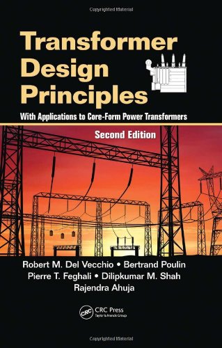
Robert M. Del Vecchio, Bertrand Poulin, Pierre T. Feghali, Dilipkumar M. Shah, Rajendra Ahuja9781439805824, 1439805822
Simplifies presentation and emphasizes fundamentals, making it easy to apply presented results to your own designs
The models, formulae, and methods illustrated in this book cover the crucial electrical, mechanical, and thermal aspects that must be satisfied in transformer design. The text also provides detailed mathematical techniques that enable users to implement these models on a computer. The authors take advantage of the increased availability of electromagnetic 2D and 3D finite element programs, using them to make calculations, especially in conjunction with the impedance boundary method for dealing with eddy current losses in high-permeability materials such as tank walls.
Includes new or updated material on:
– Multi terminal transformers
– Phasors and three-phase connections
– Impulse generators and air core reactors
– Methodology for voltage breakdown in oil
– Zig-zag transformers
– Winding capacitances
– Impulse voltage distributions
– Temperature distributions in the windings and oil
– Fault type and fault current analyses
Although the book’s focus is on power transformers, the transformer circuit models presented can be used in electrical circuits, including large power grids. In addition to the standard transformer types, the book explores multi-terminal transformer models, which allow complicated winding interconnections and are often used in phase shifting and rectifying applications. With its versatile coverage of transformers, this book can be used by practicing design and utility engineers, students, and anyone else who requires knowledge of design and operational characteristics.
Table of contents :
TRANSFORMER DESIGN PRINCIPLES: With Applications to Core-Form Power Transformers……Page 2
CONTENTS……Page 4
PREFACE……Page 10
TABLE OF CONTENTS……Page 0
1.1 HISTORICAL BACKGROUND……Page 11
1.2 USES IN POWER SYSTEMS……Page 13
1.3 CORE-FORM AND SHELL-FORM TRANSFORMERS……Page 19
1.4 STACKED AND WOUND CORE CONSTRUCTION……Page 20
1.5 TRANSFORMER COOLING……Page 25
1.6 WINDING TYPES……Page 27
1.7 INSULATION STRUCTURES……Page 30
1.8 STRUCTURAL ELEMENTS……Page 34
1.9 THREE PHASE CONNECTIONS……Page 39
1.10 MODERN TRENDS……Page 46
2.1 INTRODUCTION……Page 49
2.2 BASIC MAGNETISM……Page 52
2.3 HYSTERESIS……Page 56
2.4 MAGNETIC CIRCUITS……Page 59
2.5 INRUSH CURRENT……Page 64
2.6 TRANSFORMER CIRCUIT MODEL WITH CORE……Page 76
2.7 PER UNIT SYSTEM……Page 90
2.8 VOLTAGE REGULATION……Page 92
3.1 INTRODUCTION……Page 96
3.2 IDEAL TRANSFORMERS……Page 97
3.2.1 Ideal Autotransformer……Page 101
3.3 LEAKAGE IMPEDANCE FOR 2-WINDING TRANSFORMERS……Page 103
3.3.1 Leakage Impedance for a 2-Winding utotransformer……Page 107
3.4 LEAKAGE IMPEDANCES FOR 3-WINDING TRANSFORMERS……Page 108
3.4.1 Leakage Impedances for an Autotransfonner with Tertiary……Page 113
3.4.2 Leakage Impedance between 2 Windings Connected in Series and a Third Winding……Page 118
3.4.3 Leakage Impedance of a 2-Winding Autotransformer with XLine Taps……Page 119
3.4.4 More General Leakage Impedance Calculations……Page 122
3.5 TWO WINDING LEAKAGE REACTANCE FORMULA……Page 123
4.1 INTRODUCTION……Page 127
4.2 SYMMETRICAL COMPONENTS……Page 129
4.3 FAULT ANALYSIS ON 3-PHASE SYSTEMS……Page 135
4.3.1 3-Phase Line to Ground fault……Page 137
4.3.2 Single Phase Line to Ground Fault……Page 138
4.3.3 Line to Line Fault……Page 139
4.3.4 Double Line to Ground Fault……Page 140
4.4 FAULT CURRENTS FOR TRANSFORMERS WITH 2 TERMINALS PER PHASE……Page 141
4.4.1 3-Phase Line to Ground Fault……Page 143
4.4.2 Single Phase Line to Ground Fault……Page 144
4.4.4 Double Line to Ground Fault……Page 145
4.4.5 Zero Sequence Impedances……Page 146
4.5 FAULT CURRENTS FOR TRANSFORMERS WITH 3 TERMINALS PER PHASE……Page 148
4.5.2 Single Phase Line to Ground Fault……Page 151
4.5.3 Line to Line Fault……Page 152
4.5.4 Double Line to Ground Fault……Page 153
4.5.5 Zero Sequence Impedances……Page 154
4.6 ASYMMETRY FACTOR……Page 155
5.1 INTRODUCTION……Page 157
5.2 THEORY……Page 158
5.3 DETERMINING THE B-FIELD……Page 174
5.4 DETERMINING THE WINDING FORCES……Page 175
5.5 GENERAL METHOD FOR DETERMINING INDUCTANCES AND MUTUAL INDUCTANCES……Page 177
5.6 RABINS’ FORMULA FOR LEAKAGE REACTANCE……Page 183
5.7 RABINS’ METHOD APPLIED TO CALCULATE SELF AND MUTUAL INDUCTANCES OF COIL SECTIONS……Page 190
6.1 INTRODUCTION……Page 193
6.2 FORCE CALCULATIONS……Page 196
6.3 STRESS ANALYSIS……Page 198
6.3.2 Axial Bending Stress per Strand……Page 201
6.3.3 Tilting Strength……Page 205
6.3.4 Stress in Tie Bars……Page 209
6.3.5 Stress in the Pressure Rings……Page 216
6.3.6 Hoop Stress……Page 217
6.3.7 Radial Bending Stress……Page 219
6.4 RADIAL BUCKLING STRENGTH……Page 227
6.5 STRESS DISTRIBUTION IN A COMPOSITE WIRE-PAPER WINDING SECTION……Page 237
6.6 ADDITIONAL MECHANICAL CONSIDERATIONS……Page 243
7.1 INTRODUCTION……Page 245
7.2 THEORY……Page 246
7.3 STEIN’S CAPACITANCE FORMULA……Page 253
7.4 GENERAL DISK CAPACITANCE FORMULA……Page 260
7.5 COIL GROUNDED AT ONE END WITH GROUNDED CYLINDERS ON EITHER SIDE……Page 261
7.6 STATIC RING ON ONE SIDE OF DISK……Page 264
7.7 TERMINAL DISK WITHOUT A STATIC RING……Page 265
7.8 CAPACITANCE MATRIX……Page 266
7.9 TWO END STATIC RINGS……Page 269
7.10 STATIC RING BETWEEN THE FIRST TWO DISKS……Page 273
7.11.1 Analytic Formula……Page 274
7.11.2 Circuit Model……Page 278
7.11.3 Experimental Methods……Page 284
7.11.4 Results……Page 285
7.12 MULTI-START WINDING CAPACITANCE……Page 289
8.1 INTRODUCTION……Page 293
8.2 PRINCIPLES OF VOLTAGE BREAKDOWN……Page 294
8.3 INSULATION COORDINATION……Page 306
8.4 CONTINUUM MODEL OF WINDING USED TO OBTAIN THE IMPULSE VOLTAGE DISTRIBUTION……Page 311
8.5.1 Circuit Description……Page 321
8.5.2 Mutual and Self Inductance Calculations……Page 325
8.5.3 Capacitance Calculations……Page 327
8.5.4 Impulse Voltage Calculations and Experimental Comparisons……Page 328
8.5.5 Sensitivity Studies……Page 334
9.1 SIMPLE GEOMETRIES……Page 337
9.2.1 Physical Basis……Page 345
9.2.2 Conformal Mapping……Page 346
9.2.3 Schwarz-Christoffel Transformation……Page 350
9.2.4 Conformal Map for the Electrostatic Field Problem……Page 352
9.2.4.1 Electric Potential and Field Values……Page 357
9.2.4.2 Calculations and Comparison with a Finite Element Solution……Page 364
9.2.4.3 Estimating Enhancement Factors……Page 368
9.3 FINITE ELEMENT ELECTRIC FIELD CALCULATIONS……Page 371
10.1 INTRODUCTION……Page 377
10.2 NO-LOAD OR CORE LOSSES……Page 378
10.2.2 Interlaminar Losses……Page 383
10.3.1 I2R Losses……Page 387
10.3.2 Stray Losses……Page 388
10.3.2.1 Eddy Current Losses in the Coils……Page 391
10.3.2.2 Tieplate Losses……Page 395
10.3.2.3 Tieplate and Core Losses Due to Unbalanced Currents……Page 405
10.3.2.4 Tank and Clamp Losses……Page 412
10.3.2.5 Tank Losses Due to Nearby Busbars……Page 415
10.3.2.6 Tank Losses Associated with the Bushings……Page 420
10.3.3 Winding Losses Due to Missing or Unbalanced Cross-Overs……Page 426
11.1 INTRODUCTION……Page 437
11.2 THERMAL MODEL OF A DISK COIL WITH DIRECTED OIL FLOW……Page 439
11.2.1 Oil Pressures and Velocities……Page 441
11.2.2 Oil Nodal Temperatures and Path Temperature Rises……Page 446
11.2.3 Disk Temperatures……Page 448
11.3 THERMAL MODEL FOR COILS WITHOUT DIRECTED OIL FLOW……Page 449
11.4 RADIATOR THERMAL MODEL……Page 452
11.5 TANK COOLING……Page 456
11.6 OIL MIXING IN THE TANK……Page 458
11.7 TIME DEPENDENCE……Page 461
11.8 PUMPED FLOW……Page 462
11.9 COMPARISON WITH TEST RESULTS……Page 463
11.10 DETERMINING M AND N EXPONENTS……Page 468
11.11 LOSS OF LIFE CALCULATION……Page 470
11.12 CABLE AND LEAD TEMPERATURE CALCULATION……Page 474
11.13 TANK WALL TEMPERATURE CALCULATION……Page 481
11.14 TIEPLATE TEMPERATURE CALCULATION……Page 483
11.15 CORE STEEL TEMPERATURE CALCULATION……Page 486
12.1 INTRODUCTION……Page 489
Separate compartment……Page 490
Plus—Minus (Reversing)……Page 491
12.4.1 Resistive Switching……Page 492
12.4.2 Reactive Switching with Preventative Autotransformer……Page 494
Fixed volts/turn……Page 496
Variable volts/turn……Page 497
12.5.2 Autotransformers……Page 498
The Series Voltage Regulator……Page 501
The Series (booster) Transformer……Page 502
12.6 GENERAL MAINTENANCE……Page 503
13.1 INTRODUCTION……Page 506
13.2 BASIC PRINCIPLES……Page 510
13.3 SQUASHED DELTA PHASE SHIFTING TRANSFORMER……Page 514
13.4 STANDARD DELTA PHASE SHIFTING TRANSFORMER……Page 521
13.5 TWO CORE PHASE SHIFTING TRANSFORMER……Page 526
13.6 REGULATION EFFECTS……Page 533
13.7 FAULT CURRENT ANALYSIS……Page 535
13.7.1 Squashed Delta Fault Currents……Page 539
13.7.2 Standard Delta Fault Currents……Page 542
14.1 INTRODUCTION……Page 550
14.2 GEOMETRIC PROGRAMMING……Page 552
14.3.1 Characterization of the Minimum……Page 559
14.3.2 Solution Search Strategy……Page 568
14.3.3 Practical Considerations……Page 574
14.4 APPLICATION TO TRANSFORMER DESIGN……Page 575
14.4.1 Design Variables……Page 576
14.4.2 Cost Function……Page 577
14.4.3 Equality Constraints……Page 580
14.4.4 Inequality Constraints……Page 584
14.4.5 Optimization Strategy……Page 585
REFERENCES……Page 589




Reviews
There are no reviews yet.