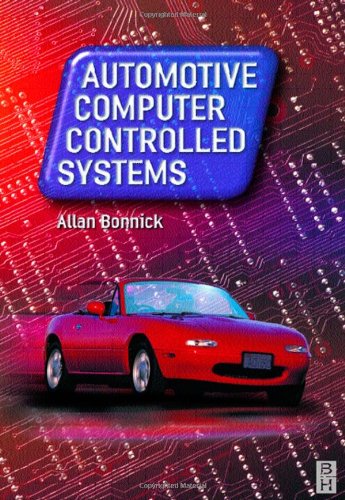
Allan Bonnick0750650893, 9780750650892
Table of contents :
1.1 Common technology……Page 14
1.3.1 THE CONSTANT ENERGY IGNITION SYSTEM……Page 15
1.3.2 DIGITAL (PROGRAMMED) IGNITION SYSTEM……Page 16
1.3.3 DISTRIBUTORLESS IGNITION SYSTEM……Page 19
1.3.4 OPTOELECTRONIC SENSING FOR THE IGNITION SYSTEM……Page 21
1.3.6 ADAPTIVE IGNITION……Page 22
1.4 Computer controlled petrol fuelling systems……Page 23
1.4.1 SINGLE-POINT INJECTION……Page 24
1.4.2 MULTI-POINT INJECTION……Page 26
1.5 Engine management systems (EMS)……Page 30
1.5.1 EXHAUST GAS RECIRCULATION……Page 31
1.6 Anti-lock braking (ABS)……Page 32
1.7 Traction control……Page 35
1.8 Stability control……Page 38
1.9 Air conditioning……Page 40
1.9.1 DEALING WITH AIR CONDITIONING REFRIGERANT……Page 42
1.11 Computer controlled diesel engine management systems……Page 43
1.11.1 SPILL CONTROL……Page 46
1.11.3 IDLE SPEED CONTROL……Page 48
1.13 Review questions……Page 51
2.1 The fundamental parts of a computer……Page 53
2.2 A practical automotive computer system……Page 54
2.3 Principles of operation……Page 57
2.4.1 DATA TRANSFERS……Page 58
2.5 Computer interfaces……Page 59
2.6 Control of output devices……Page 60
2.7 Computer memories……Page 61
2.7.1 READ ONLY MEMORIES……Page 62
2.7.3 OTHER TYPES OF COMPUTER MEMORY……Page 63
2.9 Adaptive operating strategy of the ECM……Page 64
2.10.2 STAR CONNECTED COMPUTERS……Page 65
2.10.3 MESSAGES……Page 66
2.10.4 PROTOCOLS……Page 67
2.11.1 THE PRINCIPLE OF A BUS-BASED VEHICLE SYSTEM……Page 68
2.11.3 ENCODING SERIAL DATA……Page 70
2.12 Prototype network systems……Page 72
2.13 Summary……Page 75
2.14 Review questions……Page 76
3.1 Access to DTCs……Page 78
3.1.1 METHOD 1: THE DASHBOARD LAMP……Page 79
3.1.3 METHOD 3: FAULT CODE READERS AND SCAN TOOLS……Page 83
3.2 Developments in self-diagnosis……Page 91
3.2.2 OBD II……Page 92
3.3 Diagnostic equipment and limitations of DTCs……Page 94
3.4 Review questions……Page 96
4.1 Diagnostic tools that connect to ECM……Page 98
4.2 Breakout boxes……Page 107
4.3 The digital multimeter……Page 108
4.4 Portable flat screen oscilloscopes……Page 109
4.5 Diagnostic tool and oscilloscope combined……Page 110
4.6.1 VACUUM PUMPS AND GAUGES……Page 112
4.9 Sources of diagnostic data……Page 116
4.10.1 PETROL ENGINE EMISSIONS……Page 118
4.10.2 DIESEL ENGINE EMISSIONS……Page 121
4.11 Review questions……Page 123
5.1.1 THE VARIABLE RELUCTANCE TYPE SENSOR……Page 125
5.1.2 HALL EFFECT SENSORS……Page 129
5.2 Optical sensors……Page 131
5.3 Combustion knock sensors……Page 132
5.4 Variable resistance type sensors……Page 134
5.5 Temperature sensors……Page 137
5.6 Ride height control sensor……Page 138
5.7 Manifold absolute pressure (MAP)……Page 139
5.7.1 THE VARIABLE VOLTAGE MAP SENSOR……Page 140
5.7.2 OTHER MAP SENSORS……Page 142
5.8 Exhaust gas oxygen sensors……Page 143
5.8.1 THE VOLTAIC-TYPE EGO SENSOR……Page 145
5.8.2 THE RESISTIVE-TYPE EGO SENSOR……Page 150
5.9 Air flow measurement……Page 151
5.9.1 HOT WIRE MASS AIR FLOW SENSOR (MAF)……Page 155
5.11 Review questions……Page 157
6.1 Actuator operation……Page 159
6.2.2 MULTI-POINT PETROL INJECTION……Page 160
6.3.1 PEAK AND HOLD……Page 162
6.3.2 CONVENTIONAL SWITCHING TO EARTH……Page 163
6.3.3 PULSE WIDTH MODULATED INJECTORS……Page 165
6.4 Exhaust gas recirculation……Page 167
6.5 Petrol engine idle speed control……Page 168
6.5.1 STEPPER MOTOR-OPERATED VALVE……Page 170
6.5.2 SOLENOID-OPERATED VALVE……Page 173
6.7 ABS actuators……Page 174
6.8 A clamping diode……Page 175
6.9 Electronic unit injectors……Page 176
6.10 Review questions……Page 178
7.1 Circuit testing……Page 181
7.2 Vehicle specific details……Page 185
7.3 The ‘six-steps’ approach……Page 186
7.4 Skills required for effective diagnosis……Page 187
7.5 An approach to fault finding……Page 188
7.6.1 OXYGEN SENSOR……Page 192
7.6.2 KNOCK SENSORS……Page 199
7.6.3 AIR FLOW METERS……Page 200
7.6.4 THROTTLE POSITION SWITCHES……Page 203
7.6.5 A COOLANT TEMPERATURE SENSOR……Page 205
7.6.6 MANIFOLD ABSOLUTE PRESSURE SENSOR (MAP) TESTS……Page 208
7.7.1 TESTS ON DISTRIBUTORLESS IGNITION DIS……Page 211
7.8 Diesel injection……Page 213
7.9 Sensor tests on other systems……Page 215
7.9.1 ABS WHEEL SPEED SENSORS……Page 216
7.9.2 TESTING THE RIDE HEIGHT CONTROL SENSOR……Page 219
7.10 Intermittent faults……Page 220
7.10.1 FLIGHT RECORDER (DATA LOGGER) FUNCTION……Page 221
7.11 Summary……Page 222
7.12 Review questions……Page 223
8.1 Partial and absolute pressures……Page 225
8.2 The piezoelectric effect……Page 226
8.3 Liquid crystal displays……Page 227
8.5.1 THE RTL NOR GATE……Page 229
8.5.2 TRUTH TABLES……Page 230
8.5.3 THE SR (SET, RESET) FLIP-FLOP……Page 231
8.5.4 ANALOGUE TO DIGITAL CONVERSION……Page 234
8.5.5 DIGITAL TO ANALOGUE CONVERSION……Page 235
8.6 OBD II……Page 236
8.6.1 FUEL SYSTEM LEAKAGE……Page 237
8.6.2 SECONDARY AIR INJECTION……Page 238
8.6.4 STANDARDIZED FAULT CODES……Page 239
8.8 Supplementary restraint systems (SRS)……Page 240
8.8.1 HANDLING SRS COMPONENTS……Page 243
8.9 The coded ignition key……Page 244
8.11 Precautions when working with computer controlled systems……Page 245
8.12 Variable capacitance sensor……Page 246
8.13 Optoelectronics……Page 247
8.14 Review questions……Page 248
A.2 Answers to review questions……Page 250
A.3 OBD II standard fault codes……Page 251
Index……Page 262



Reviews
There are no reviews yet.